Dataplane Configuration
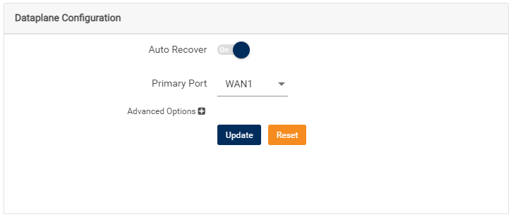
The data plane configuration applies to Edge devices running OS version 7.2.0 and above. It only supports the monitoring of links connected into WAN1 and WAN2 ports for breakout at the Edge.

|
Setting the failover timer aggressively can result in network instability, especially in lossy networks. |
The Auto Recover option, enabled by default, only restarts new data sessions on the primary link as soon as it is identified as stable. Long-lived flows are terminated on the backup link only after the switch timeout expires. The default time on the switch timeout is 7200 secs (2 hours). When these flows are re-established by the application, it will be done over the primary link.
Managing Dataplane settings
- Navigate to the CPE Management tab and open the Configuration page.
- Scroll to the Link Behavior section > Dataplane Configuration settings.
- To disable or re-enable Auto Recover functionality, toggle the button to On or Off.
- To manage a primary port, select between WAN1 and WAN2 in the Primary Port drop-down menu.
- To change the values of default monitoring properties, click Advanced Options. To revert to default settings, click Reset.
Advanced OptionsProperty Description Settings Link Down Threshold (seconds) Defines the time in which the WAN port carrying data traffic is down before declaring the WAN port unusable. Default: 30
Min: 1
Max: 120Link Up Threshold (seconds) Defines the time in which the WAN port carries data traffic before declaring the WAN port usable. Default: 30
Min: 1
Max: 120Unstable Window (seconds) Defines the length of the unstable window (must be equal or greater than Link Up Threshold). The unstable window is created when the WAN port carrying data traffic loses internet reachability.
This event is independent of the Link Down Threshold. The window must end after the WAN port has carried traffic for a minimum of Link Up Threshold.
Default: 60
Min: 1
Max: 120Switch Timeout (seconds) Defines the maximum time required for transferring flows from the primary to the backup WAN port or vice-versa. Upon timeout, all flows not transferred are terminated. Default: 7200
Min: 10
Max: 7200Connectivity List (number of strings) The IP addresses used to validate Internet reachability from the WAN ports. Default: 8.8.8.8, 8.8.4.4, and 1.1.1.1
Min: 1 IP address
Max: 5 IP addressesConnectivity Fail Threshold (percent) This percentage is the threshold of packet loss (ping loss) the Internet link test meet to declare the test successful. Hence, declaring the WAN port can reach the internet. Default: 100
Min: 10
Max: 100Connectivity Test Window (seconds) Time required to ping a single server listed in Connectivity List. Default: 5
Min: 1
Max: 20Connectivity Test Frequency (seconds) Frequency of the ping test.
Default: 60
Min: 2
Max: 60
- To save and apply changes, first, click Update and then click Save Configuration.
Configuring failover timer
In Internet Breakout, the state machine manages link failover, and its ability to do so is governed by the following parameters. They are configurable and dictate the speed at which a link fails over to the backup link.- Connectivity Test Frequency – Frequency of the ping test in seconds.
- Connectivity Test Window – Time is seconds to ping a single server listed in Connectivity List.
- Link Down Threshold – Number of seconds the WAN port carries data traffic before declaring the WAN port unusable.
Achieving a minimum failover time requires decreased values for these parameters. The following example will illustrate how these values help to get desired failover time. Consider a scenario where the required failover time is 15 seconds. To achieve this failover time, the testing frequency must be increased and the test window reduced.

|
Increasing the test frequency and reducing the test window increases the amount of network packet probes sent over the Internet links. |
Therefore, changing the test frequency to 2 seconds and updating the test window to 4 seconds will achieve a 15-second failover time as subsequent tests fail beyond the link down threshold of 13 seconds.
The following table illustrates the modifications required for each parameter to achieve the desired failover time.
Failover Time (seconds) | Configuration (seconds) |
| 15 | Connectivity Test Frequency – 2 Connectivity Test Window – 4 Link Down Threshold – 13 |
| 30 | Connectivity Test Frequency – 4 Connectivity Test Window – 2 Link Down Threshold – 26 |
| 60 | Connectivity Test Frequency – 4 Connectivity Test Window – 2 Link Down Threshold – 56 |
TERMS OF USE | ANTI SPAM | PRIVACY POLICY | USER LICENSE AGREEMENT | PATENTS