Package Components
The following components are shipped in the package containing the E-40. If you note any of the below-listed components missing or damaged, please contact support.
- SC//Connect™ | Edge E-40 x 1
- Power Adapter x 1
- Power Cord x 1
- Console Cable x 1
Safety
All standard electronic safety instructions apply.
- Verify that the power supply is safe and does not exceed the power adapter's specified input capacity for the device. To avoid fires and device damage, only use approved and standard cables and adapters.
- To avoid the hazard of electric shock while plugging the device into the power supply, verify that the power socket is not damaged.
- Disconnect the power while removing or making a connection.
- To clean the device, first, disconnect it from the power supply. Clean with a slightly damp cloth and avoid spraying with liquid or detergents.
- Place the device in a controlled environment with monitored levels of temperature and humidity.
-
Place the unit on a rack or on top of a shelf in a ventilated room. The E-40 is passively cooled: the device is designed as a fanless system with an aluminum enclosure, which helps to dissipate the heat to the external environment quickly and efficiently. The supported thermal operating environment is up to 40°C (100F), and the E-40 with high loads can run as hot as 60°C (140F). We advise that it should be placed on a flat, solid surface in the open and not in a non-ventilated enclosure. Refrain from putting any objects on top of the E-40.
- If you observe that the device is damaged or not operating in the described manner, please reach out to Support.
Installing E-40
Before proceeding with the installation, locate the internet circuits that will be connected to the E-40 and test internet reachability and run speed tests by direct connection to a laptop or desktop. Record the speed test values on each circuit for download/upload. See Installation Best Practices.
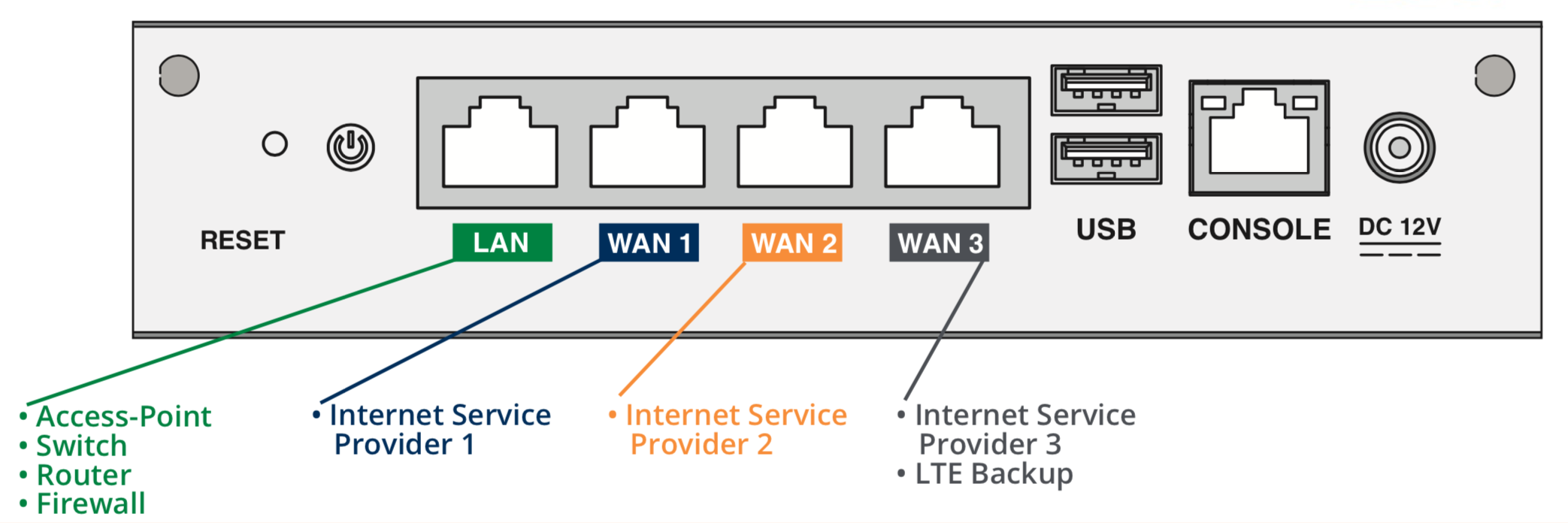
- Connect your primary Internet circuit to the WAN1 Port.
- Connect the backup and subsequent Internet circuits to the remaining available WAN ports.
- Connect a USB dongle or the SIM for the built-in modem if available.
- Connect either your firewall, router, or switch to the LAN port.
-
Power on the device, then complete the installation by logging in to SC//Connect™ Orchestrator to complete the Service Order setup, configure the device, and deploy it.
For more information, see Service Orders and Site Configuration Management.
Post-installation Activities
- After completing the installation, verify that the site is online in SC//Connect™ Orchestrator.
-
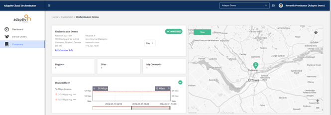
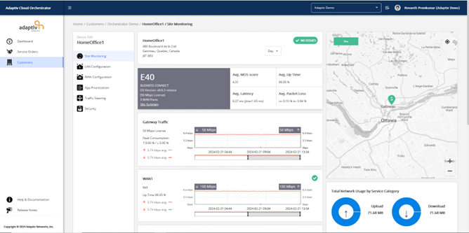
In the orchestrator, on the customer dashboard, check the customer and site status as shown below. A successful installation and deployment are indicated by the "No Issues" message in the customer information section and a green checkmark in the site section.
-
Click the site name for detailed information about the site, such as the status of individual WAN connections, QoE score, and network usage.
SC//Connect™ | Edge E-40 Specifications
| Front Panel |
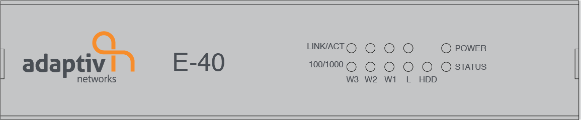
The Front Panel consists of the following components (Left to Right View).
Front Panel LED Key (Left to Right View)
|
||||||||||||||
| Back Panel |
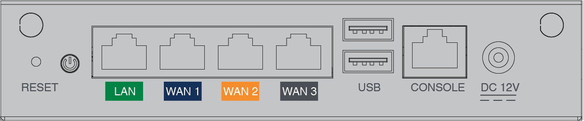
The Back Panel consists of the following components (Left to Right View).
Back Panel LED Key (Left to Right View)
|