---
title: "SC//Connect™ Edge E-60 LTE Modem Install Guide"
id: "adaptiv-edge-e-60-lte-modem-install-guide-help"
project: "SC//Connect™ | OS v8.5"
url: "https://docs.scalecomputing.com/articles/sc-connect-os-v8-5/adaptiv-edge-e-60-lte-modem-install-guide-help"
updated: 2026-11-19T17:09:09Z
---
# SC//Connect™ Edge E\-60 LTE Modem Install Guide
# **Adaptiv | Edge E-60 LTE Modem Install Guide**
* * *
Thank you for choosing Adaptiv Networks. This Install Guide outlines the step-by-step instructions to install an LTE modem inside [Adaptiv | Edge E-60](/smart/project-e40/adaptiv-edge-e-40-install-guide-7-x)(referred to as E-60).
## **Package Components**
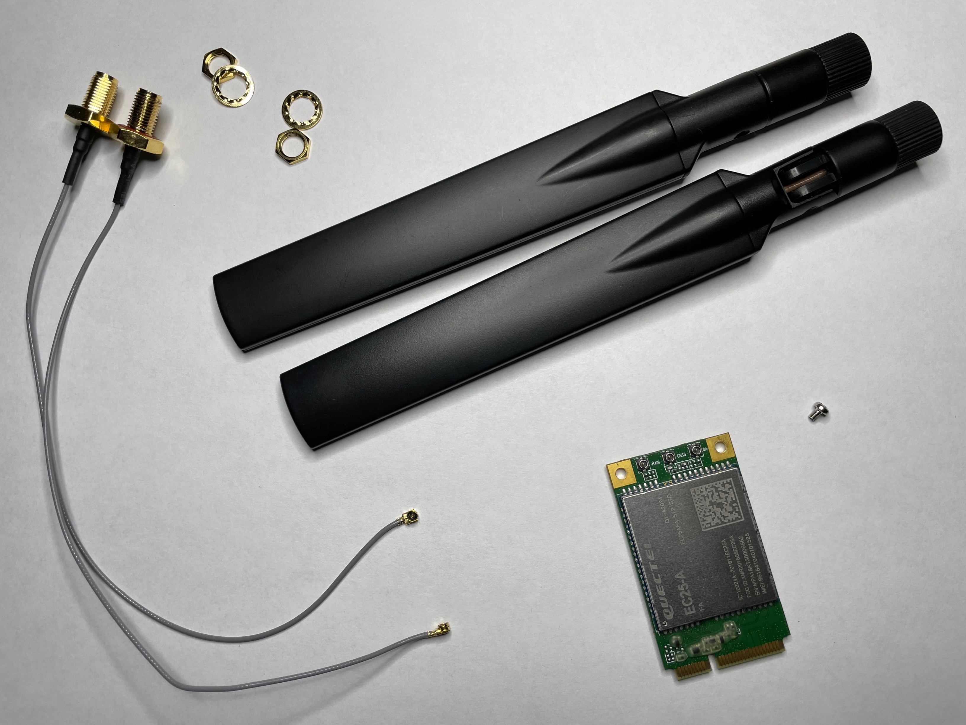
| The following components of LTE modem are shipped with E-60. Please contact [support@adaptiv-networks.com](mailto:support@adaptiv-networks.com?subject=Missing%20package%20contents:%20E40%20LTE%20Modem) to notify the missing components.
- LTE Kit – LTE modem x 1
- Antenna x 2
- Antenna cables x 2
- Antenna cable nuts x 2
- washer x 2
- fitting screw x 1
|
| --- |
## **Safety**
All standard electronic safety instructions apply.
| The installation of the LTE modem must be performed in a way that protects the integrity of the E-60 internal electronic components. We recommend that the individual installation the modem should wear a grounded ESD strap. Please make sure that the working surface is grounded. Use a Phillips screwdriver to remove and put back the E-60 components. |
| --- |
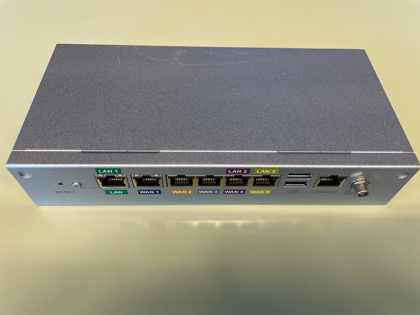
1. First, power off E-60, disconnect the power supply to the device and remove all cables connected to the network interfaces.
[](/resources/Storage/sc-connect-os-v8-5/E60%20LTE%20Modem/Step%201.jpg)
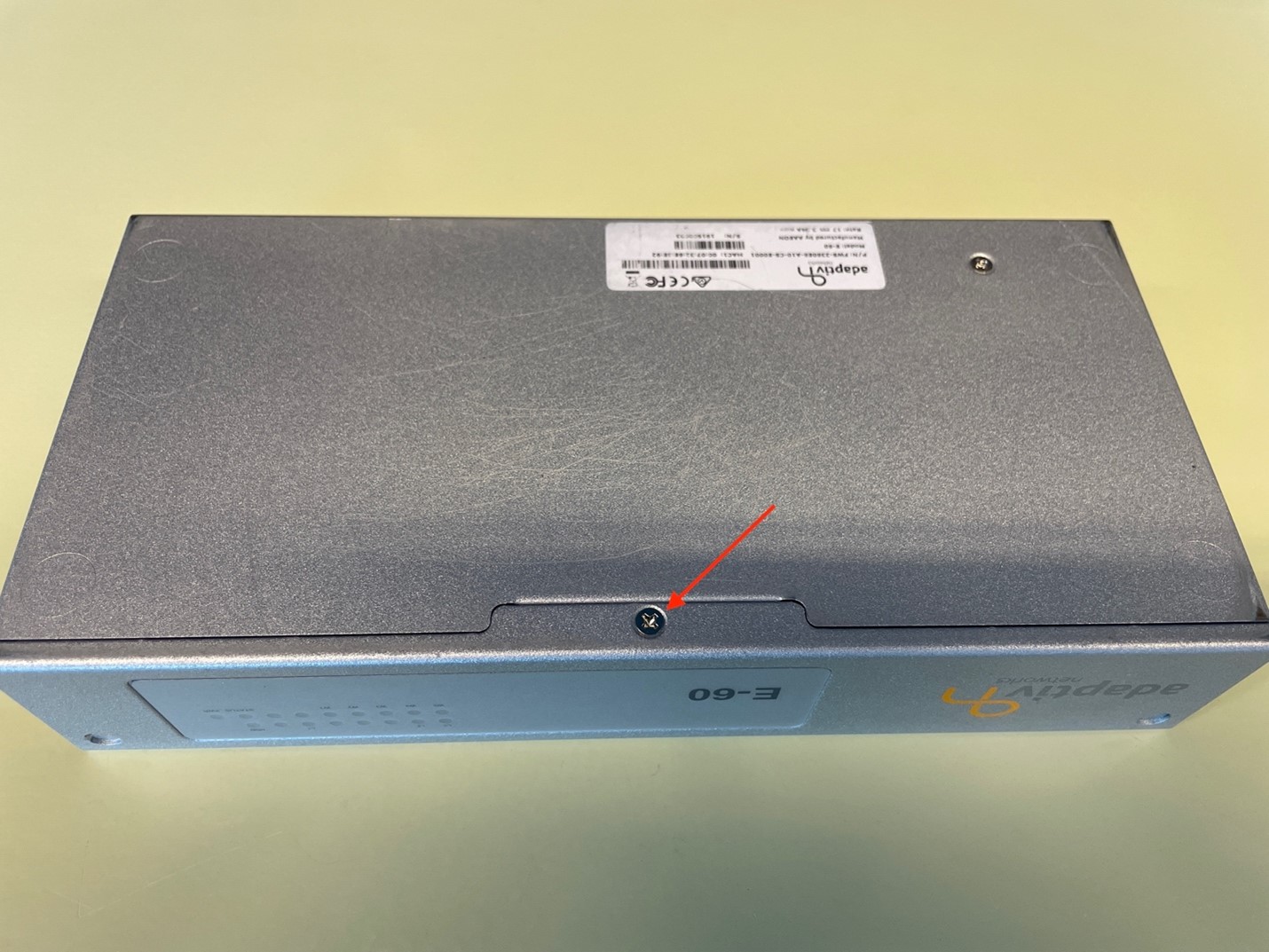
2. Flip the device such that the faceplate is facing up. Using a Phillips screwdriver, remove the screw from the faceplate and slide it.
| [](/resources/Storage/sc-connect-os-v8-5/E60%20LTE%20Modem/Step%202.jpg) | [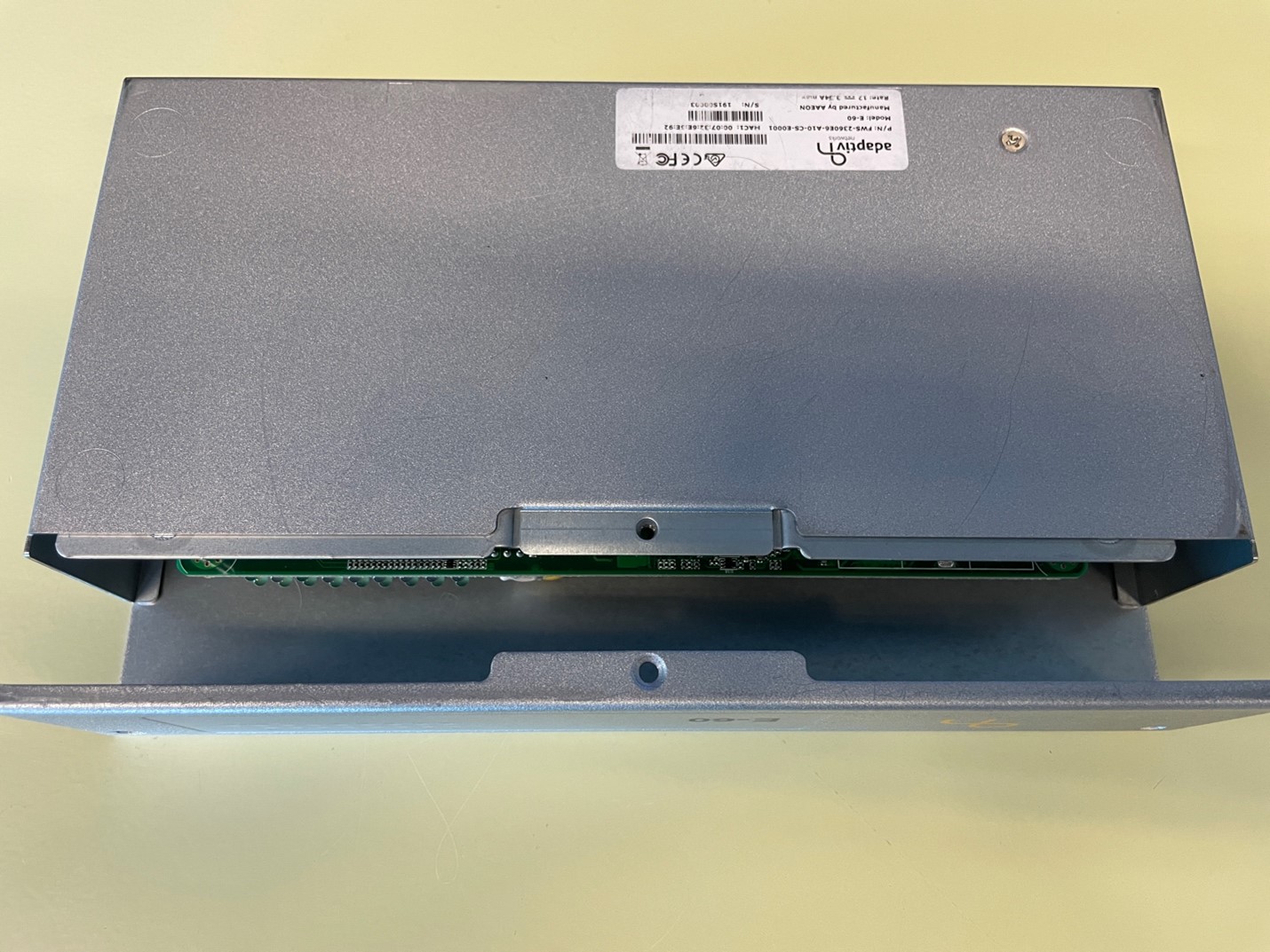](/resources/Storage/sc-connect-os-v8-5/E60%20LTE%20Modem/Step%203.jpg) |
| --- | --- |
3. Gently flip the device such that the electronic circuit board is facing up.
|  | Do not separate the electronic circuit board from clamshell. Further steps must be performed with circuit board in place and with care to avoid any damage to it. |
| --- | --- |
[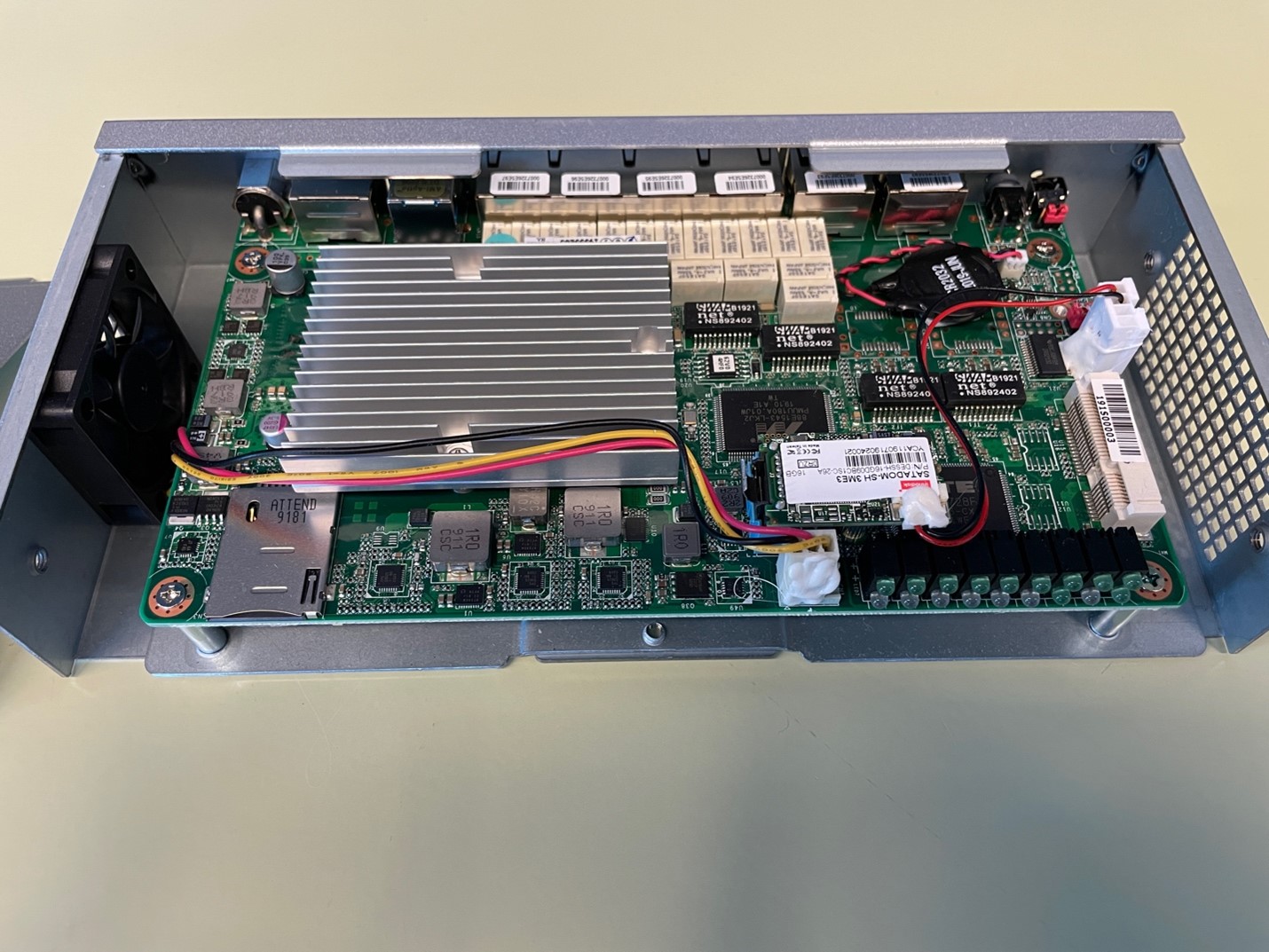](/resources/Storage/sc-connect-os-v8-5/E60%20LTE%20Modem/Step%204.jpg)
4. On the front side of the E60 device, identify the two cutouts for the LTE antenna cable. Using the screwdriver, push the cutouts back and forth and remove them.
[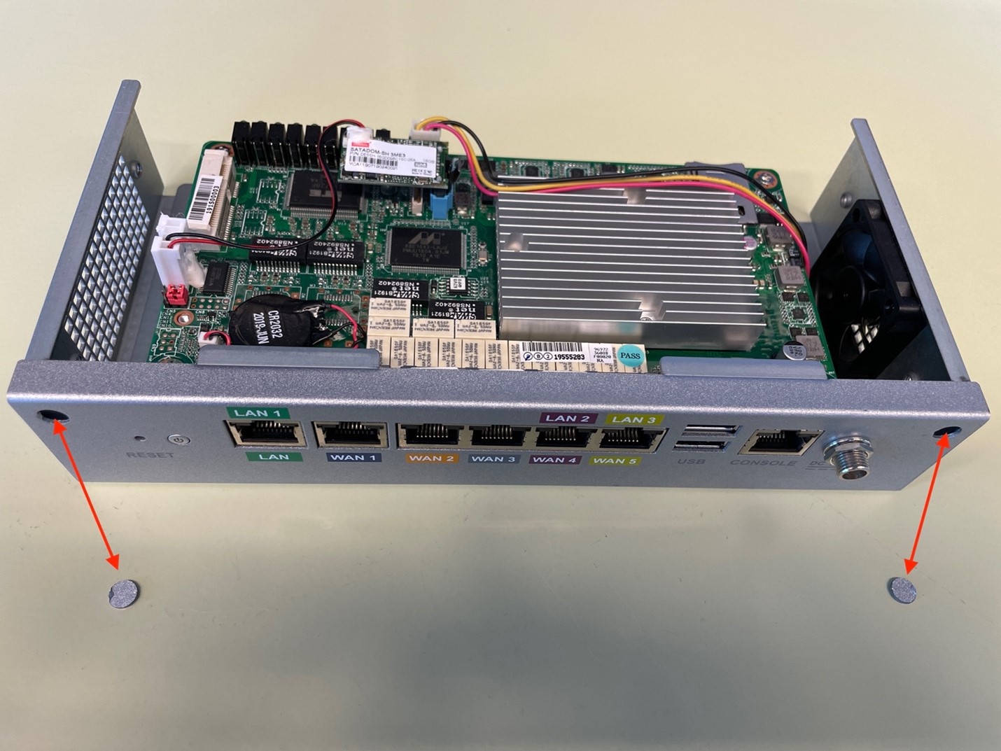](/resources/Storage/sc-connect-os-v8-5/E60%20LTE%20Modem/Step%206.jpg)
5. Now, insert an antenna cable through each cutout such that the threaded bolt is facing the front. Insert the washers in the front of the threaded bolts and then tighten the nuts securely (provided in the LTE kit) to the threaded bolts of the cable, ensuring the cables are tightly held in place.
[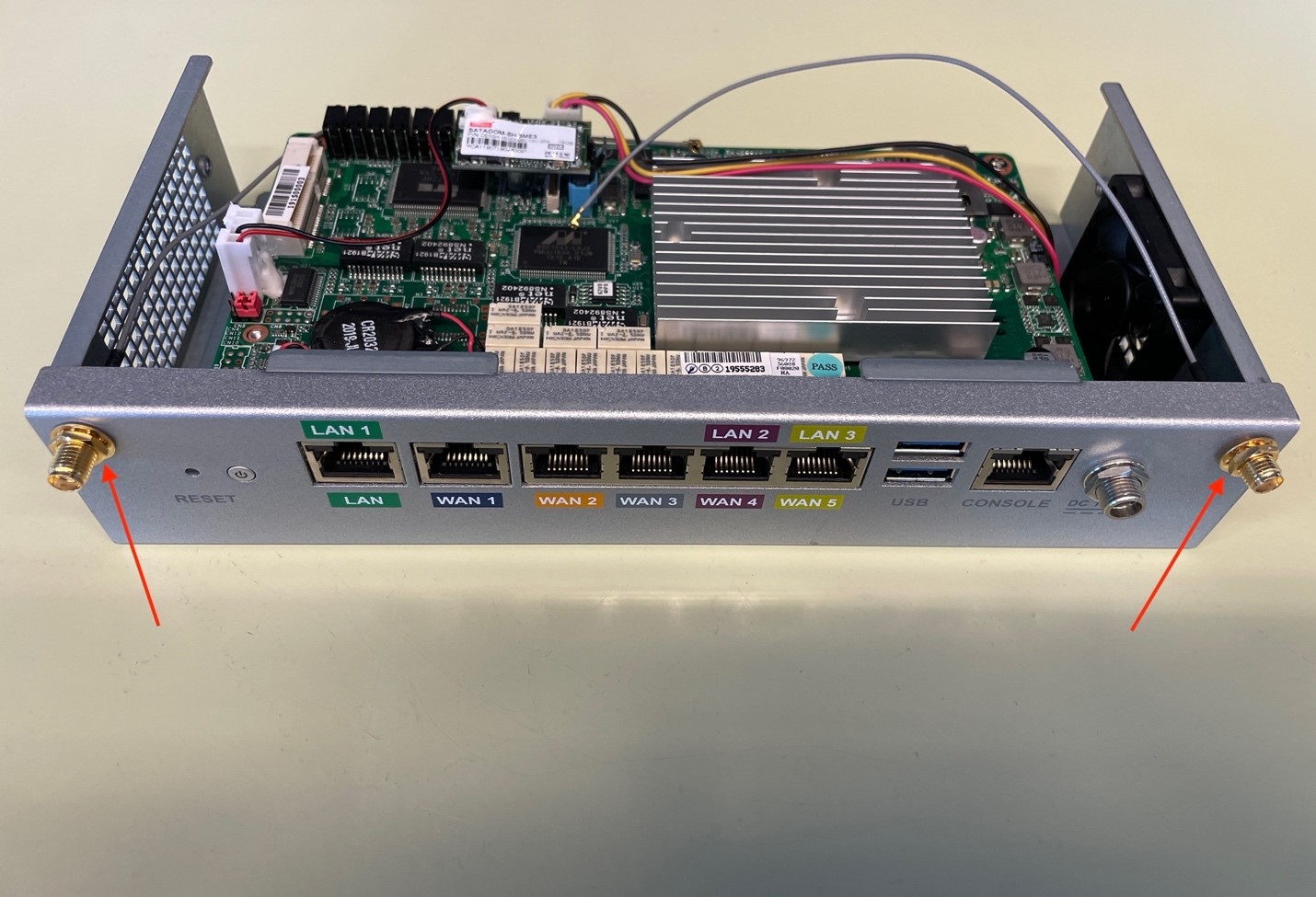](/resources/Storage/sc-connect-os-v8-5/E60%20LTE%20Modem/Step%208.jpg)
6. Attach and tighten an antennas from the LTE kit to each of the threaded bolts.
[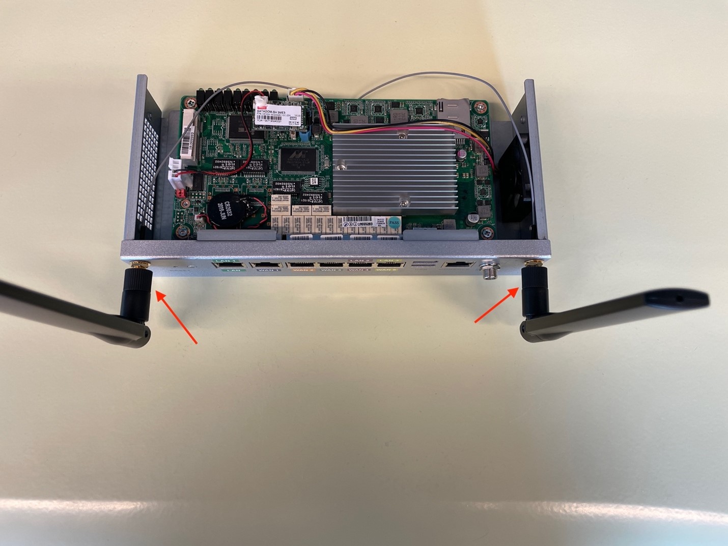](/resources/Storage/sc-connect-os-v8-5/E60%20LTE%20Modem/Step%209.jpg)
7. Now, locate the SATADOM disk on the electronic circuit board. There is a PCIe slot beneath the disk where the LTE modem will fit.
|  | Please note that the SATADOM disk is permanently attached to the circuit board and externally powered by black and red straight wires. |
| --- | --- |
[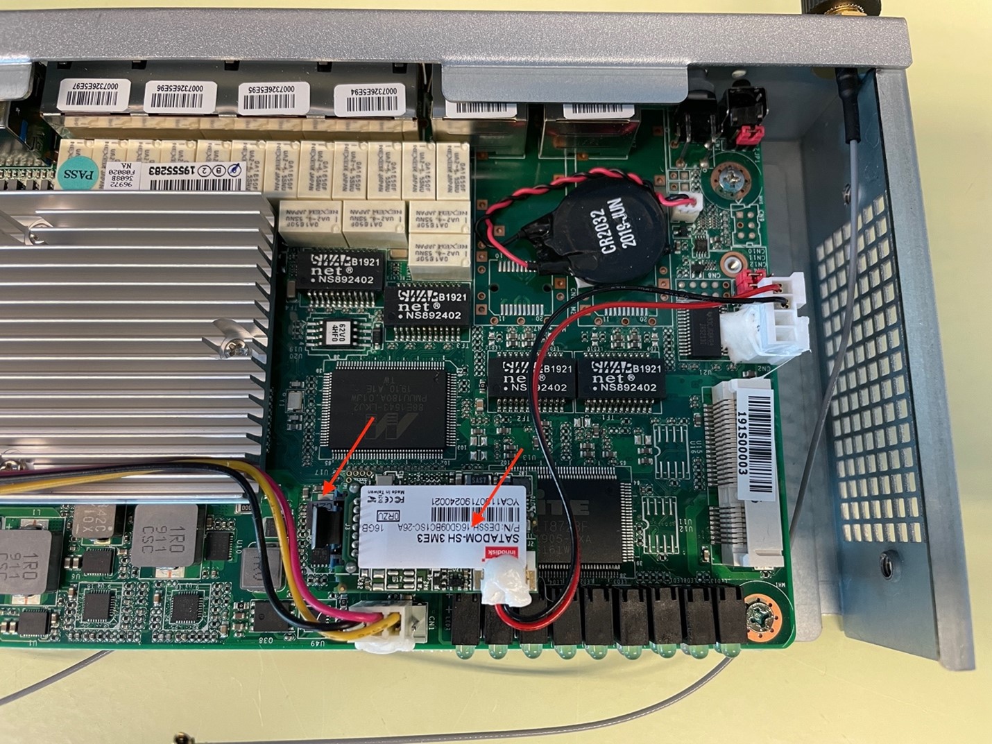](/resources/Storage/sc-connect-os-v8-5/E60%20LTE%20Modem/Step%2010.jpg)
8. Carefully release the SATADOM disk by pressing the disk metal clip. Then gently pull out the disk to disconnect it from the blue connector and move it away from the PCIe slot.
[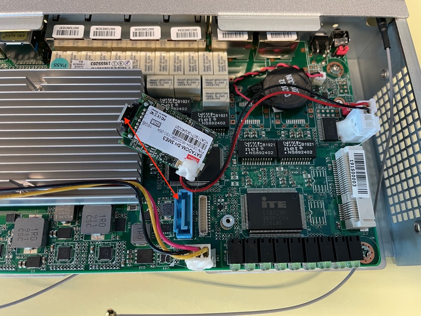](/resources/Storage/sc-connect-os-v8-5/E60%20LTE%20Modem/Step%2011.jpg)
9. Insert the LTE modem into the PCIe slot at an angle. Then push the modem gently down, and tighten it to the circuit board with the fitting screw from the LTE kit.
[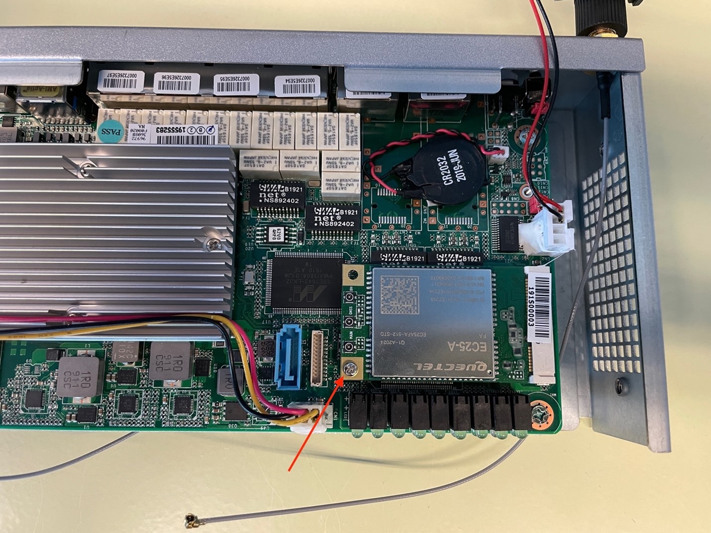](/resources/Storage/sc-connect-os-v8-5/E60%20LTE%20Modem/Step%2013.jpg)
10. Next, align the loose ends of the antenna cable ends into the LTE modem cable adaptors. Snap-fit one end into the adaptor labelled as **MAIN**and the other into the adaptor labelled as **DIV**. Please do not fit any cable into the adaptor named **GNSS**.
[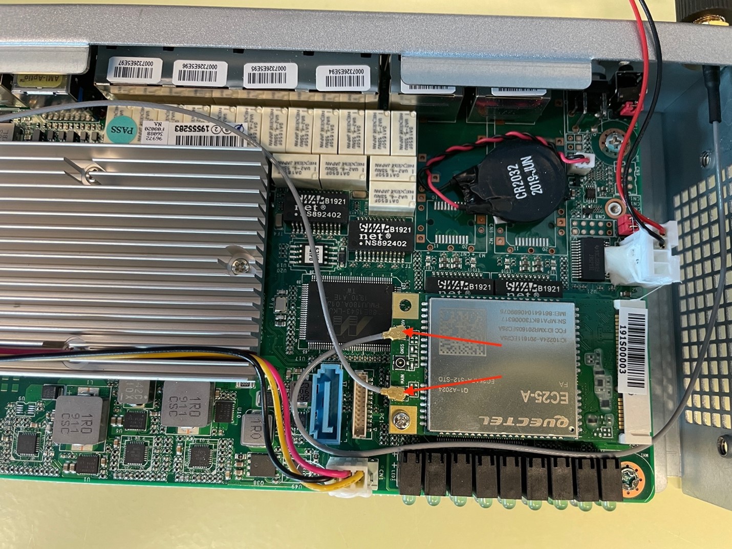](/resources/Storage/sc-connect-os-v8-5/E60%20LTE%20Modem/Step%2014.jpg)
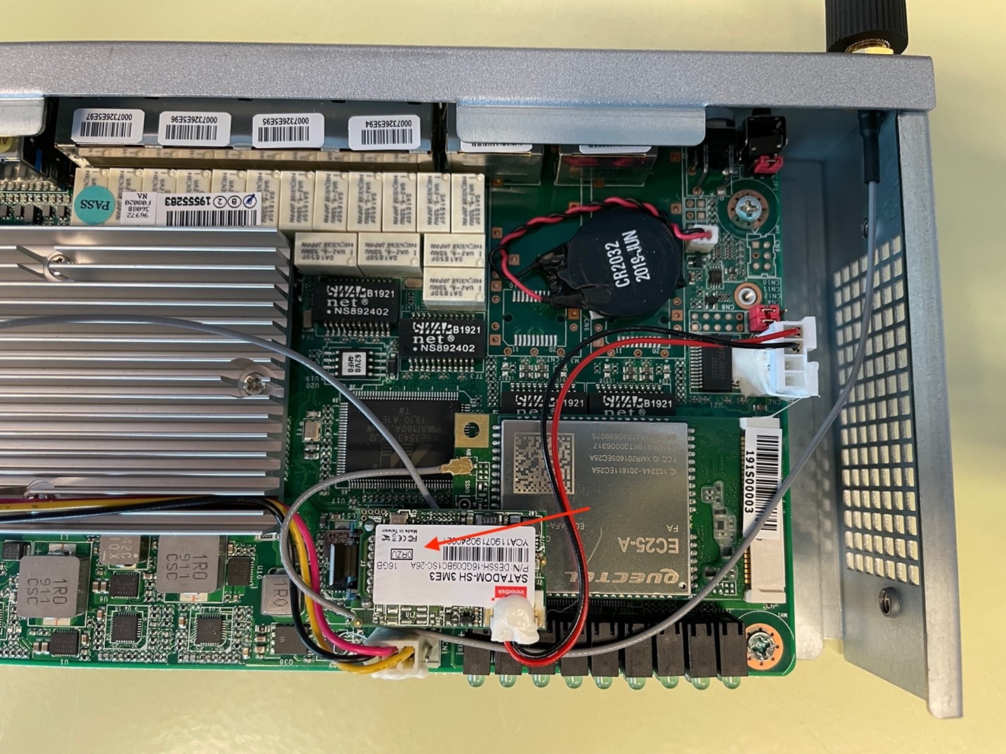
11. Place the SATADOM disk on the LTE modem adaptor and gently push it down. This action will force the metal clip back into the bracket.
[](/resources/Storage/sc-connect-os-v8-5/E60%20LTE%20Modem/Step%2015.jpg)
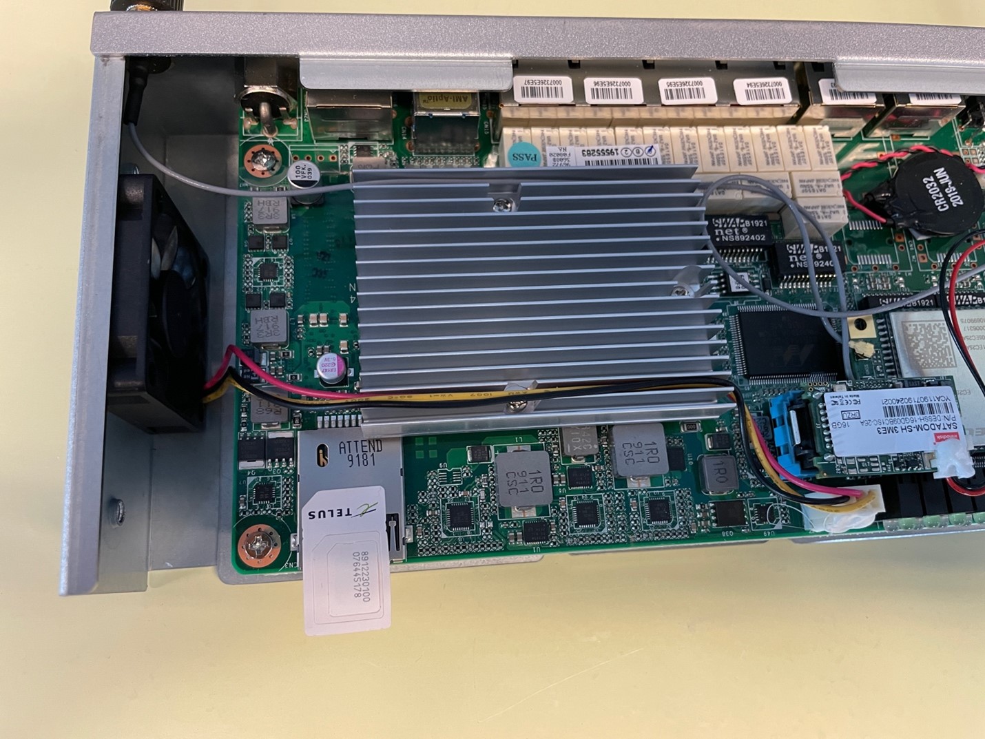
12. Align the SIM as shown in the image and gently push it into the SIM tray. If the alignment is proper, you should hear a click sound.
| [](/resources/Storage/sc-connect-os-v8-5/E60%20LTE%20Modem/Step%2016.jpg) | [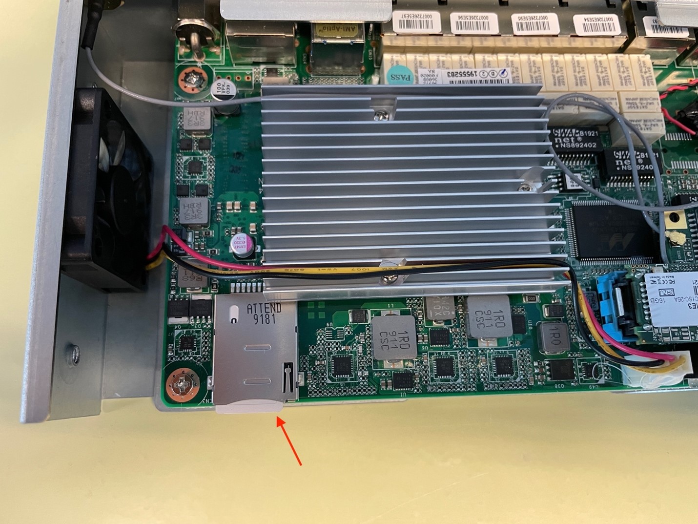](/resources/Storage/sc-connect-os-v8-5/E60%20LTE%20Modem/Step%2017.jpg) |
| --- | --- |
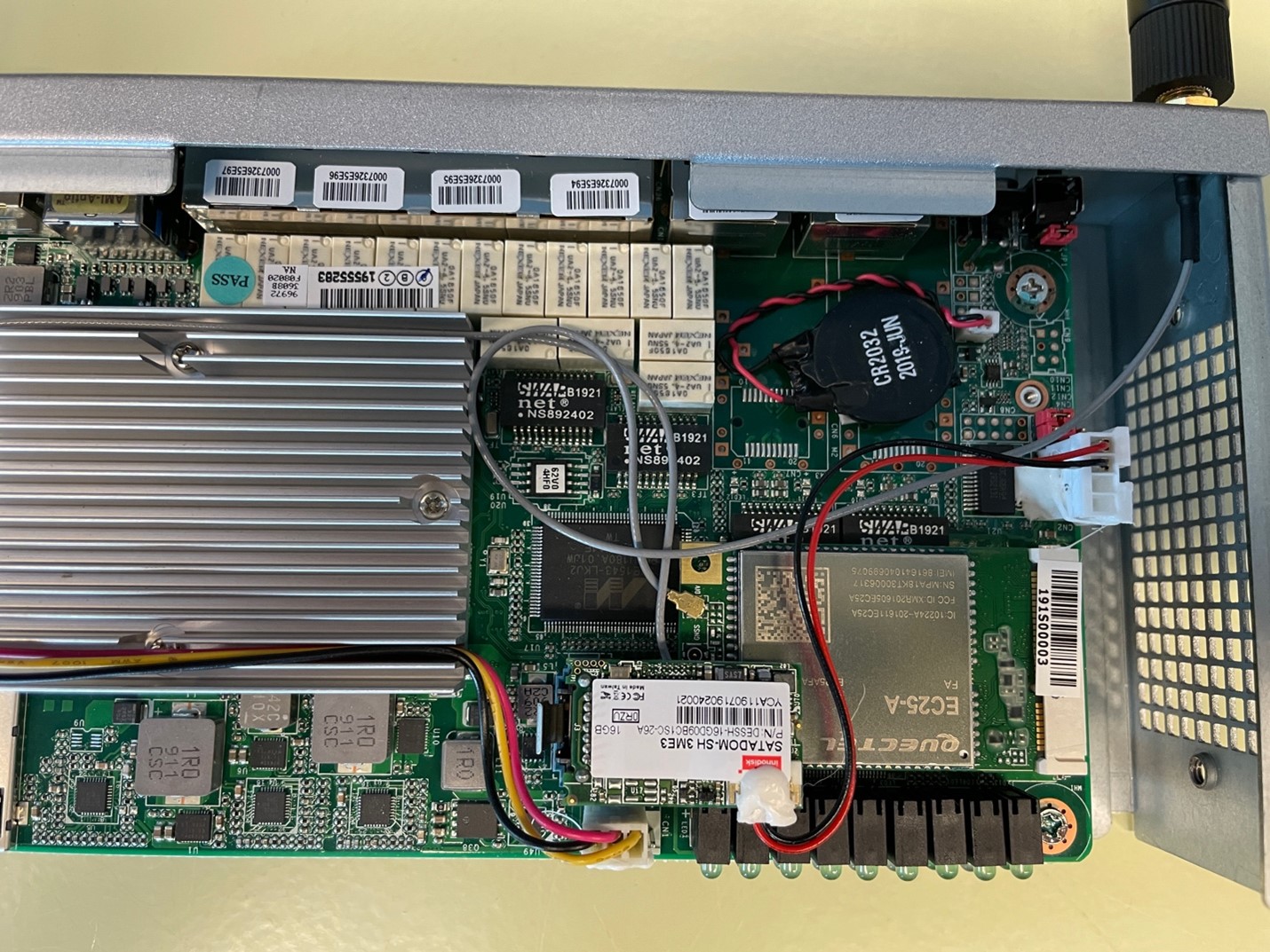
13. Gently place the wires of the antenna cables in the center of the circuit board such that they stay in place when the clamshell closes.
[](/resources/Storage/sc-connect-os-v8-5/E60%20LTE%20Modem/Step%2018.jpg)
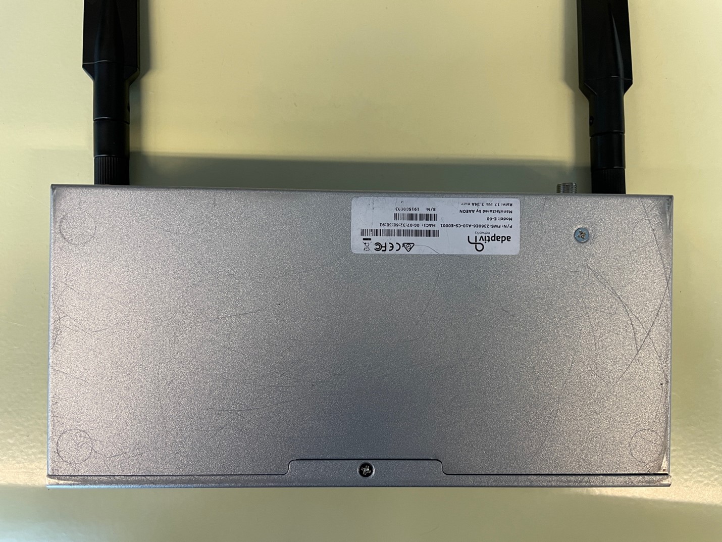
14. Next, slide back the faceplate to close the electronic circuit board and complete the assembly by tightening the screw on the faceplate.
[](/resources/Storage/sc-connect-os-v8-5/E60%20LTE%20Modem/Step%2020.jpg)