The Scale Computing™ SG2v1 edge security device (ESD) is the current-generation SG platform for connecting a site to SC//AcuVigil™. It is a fanless, cast-aluminum appliance with six gigabit Ethernet ports — two WAN-capable uplinks and a four-port LAN switch — plus a USB host port and an external 1-Wire sensor bus. SG2v1 is the full hardware name, combining the model and its revision, and is what appears on labels, packaging, and in the SKU list. This page uses the full name throughout, because later hardware revisions will differ and a bare model name would become ambiguous.
The SG2v1 is a derivative of the Silicom Rogue-2 platform, customized for Scale Computing with a second WAN port, an external hardware watchdog, capacitor-backed secure memory, a tamper switch, and an enclosure that matches the trade dress of the rest of the SG family.
Overview
Every user-accessible port and indicator is on a single I/O panel along one long edge of the device. From left to right, the panel carries the four status LEDs, the recessed button, the USB 2.0 Type-A port, the sensor bus connector, Ethernet WAN 2/OPT, Ethernet WAN 1, Ethernet LAN 1–4, and the locking 12VDC power input. For what each LED means, see Understanding the LED lights.
The status LEDs are mirrored to the top of the enclosure, so they stay readable when the device is rack-mounted or placed on a shelf and the I/O panel faces away from you. The top overlay carries the same LED legend and port map as the panel, along with the unit serial number and an installation QR code.
The base and top are finned cast aluminum. Internal components are thermally coupled to the base for heat dissipation, so both surfaces get warm in normal operation. The underside has four rubber feet, a wall-mount keyhole slot with a secondary anti-lift screw, and DIN-clip screw bosses cast into the housing.
See Dimensions for the drawing.
Understanding the LED lights
The SG2v1 has four green LEDs, labeled DIAG, SEC, CLOUD, and PWR. The same four LEDs appear on the I/O panel and on the top of the enclosure — they are mirrored, not independent, so both sets always show the same state.
PWR is driven directly by the power rails. The other three are controlled by software through CPU GPIOs.
| LED | Label icon | Indicates |
|---|---|---|
| DIAG | Warning triangle | On while the ESD is writing its configuration to storage. |
| SEC | Padlock | On: at least one VPN tunnel is up. Off: no VPN tunnel is up. |
| CLOUD | Cloud | On: the ESD is reporting to SC//AcuVigil™. Off: its last attempt to report failed. Blinking: the ESD couldn't set its clock from the internet. |
| PWR | Power symbol | The device is supplied with power. |
The RJ45 connectors have their own integrated link, speed, and activity LEDs. Those are not mirrored to the top of the enclosure.
Ports and connectors
All ports are on the I/O panel. The RJ45 connectors are all tab-up when you face the top label of the device, with the heat-sink fins pointing away from you.
| Marking | Type | Notes |
|---|---|---|
| USB | 1x USB 2.0 Type-A | Host port, 5VDC 1A. |
| SENSOR BUS | 2-position terminal block, 0.200 in (5.08 mm) pitch | 1-Wire sensor bus. Accepts a sensor dongle that breaks out temperature probes and two door contacts. |
| ETHERNET WAN 2/OPT | 1x 1GbE RJ45 | Second WAN-capable port, for failover or load balancing. Marvell 88E1512 PHY. |
| ETHERNET WAN 1 | 1x 1GbE RJ45 | Primary uplink. Microchip LAN7800 USB-to-Ethernet controller. |
| ETHERNET LAN 1–4 | 4x 1GbE RJ45 | Integrated four-port gigabit switch. |
| 12VDC | Locking barrel jack | Accepts the supplied 40 W external power supply only. |
A recessed, software-programmable button sits on the I/O panel between the LEDs and the USB port, behind a pinhole. Its function is determined by the device software; Scale Computing Support uses it for a factory reset.
MAC addresses are assigned sequentially across the Ethernet ports. The base MAC address belongs to the leftmost Ethernet port, WAN 2/OPT, incrementing left to right and ending with LAN 4 on the right.
Note: The console port, microSD slot, and M.2 expansion slot are internal and deliberately not accessible from outside the enclosure. Opening the device asserts the tamper switch. See Tamper detection and secure memory. |
Specifications
| Feature | Specification |
|---|---|
| CPU | Marvell Armada 3700 (88F3720), 2-core ARMv8 Cortex-A53, 1.2 GHz |
| Memory | 4 GB DDR4. Not all 4 GB is available to workloads, due to system overhead. |
| Storage | 16 GB eMMC 5.0 |
| Boot flash | 4 MB SPI flash |
| WAN | WAN 1: 1GbE RJ45 (Microchip LAN7800) WAN 2/OPT: 1GbE RJ45 (Marvell 88E1512) |
| LAN | 4x 1GbE RJ45 (Marvell 88E6141 switch) |
| USB | 1x USB 2.0 Type-A, 5VDC 1A |
| Sensor bus | 1-Wire sensor bus on a 2-position terminal block, 0.200 in (5.08 mm) pitch |
| Expansion | M.2 B-key, 42 mm, PCIe, intended for NVMe. Internal, not field-accessible. |
| Removable media | microSD slot. Internal, retained by a ridge in the case, not field-accessible. |
| Security | Optional TPM. Tamper switch on the top cover. Capacitor-backed SRAM. |
| Real-time clock | Supported, capacitor-backed |
| Indicators | 4x green LED (PWR plus 3 software-controlled), mirrored to top and I/O panel |
| Buttons | 1x recessed, software-programmable |
| Bootloader | U-Boot with ARM Trusted Firmware |
| Operating system | Scale Computing OS image preloaded |
| Power input | +12VDC, locking barrel jack |
| Power supply | External 40 W desktop PSU, with regional AC line cord |
| Cooling | Fanless |
| Operating temperature | 0 °C to +40 °C (32 °F to 104 °F), including the external PSU |
| Dimensions | 7.25 in x 5.62 in x 1.40 in (184.15 mm x 142.83 mm x 35.56 mm), including the wall-mount tab |
| Mounting | Desktop, wall-mount, DIN clip, or rack tray |
Dimensions
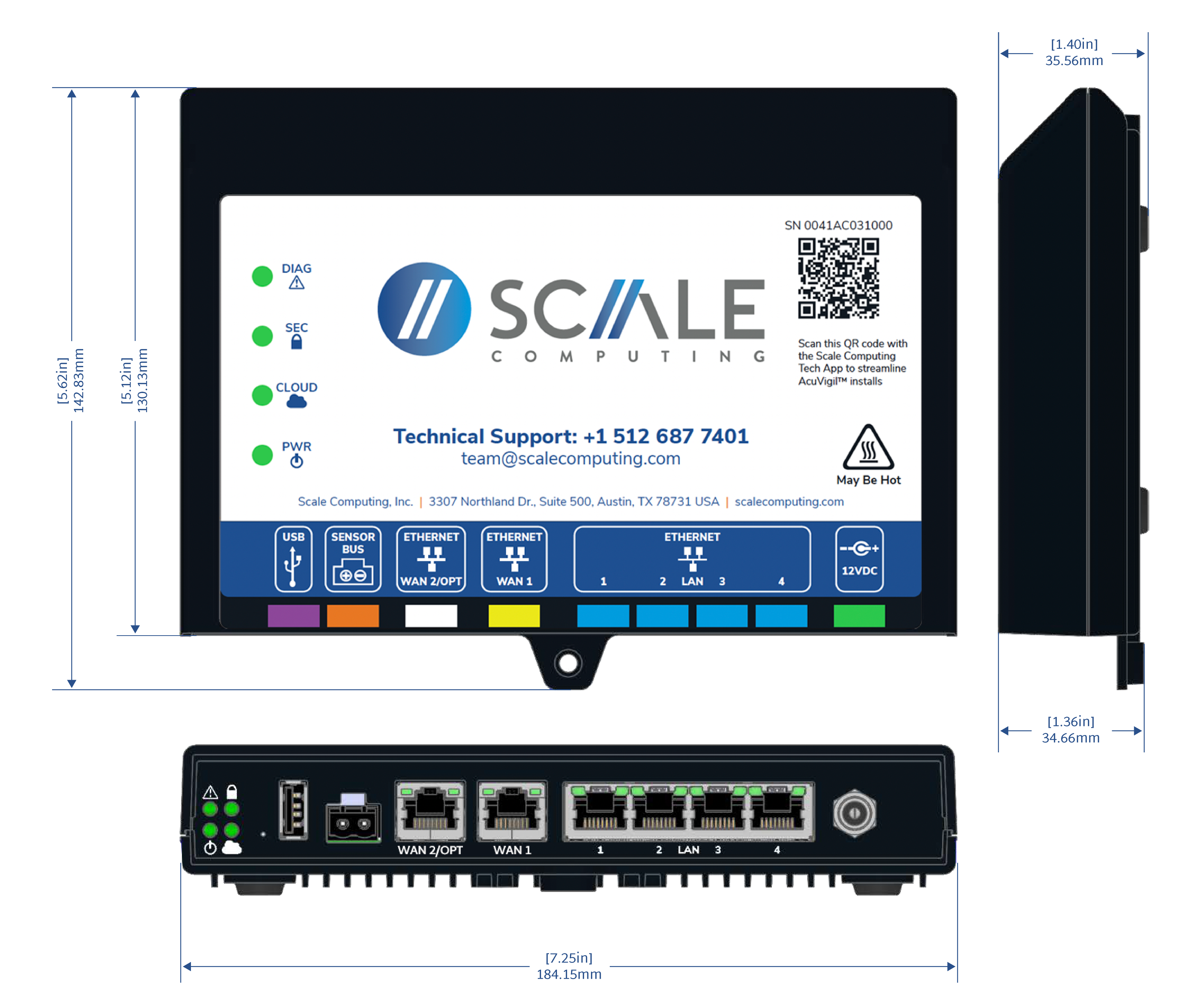
Top, side, and front dimensions. The 5.12 in (130.13 mm) figure is the body depth; 5.62 in (142.83 mm) includes the wall-mount tab. Body height is 1.36 in (34.66 mm), and 1.40 in (35.56 mm) over the I/O panel.
Hardware architecture
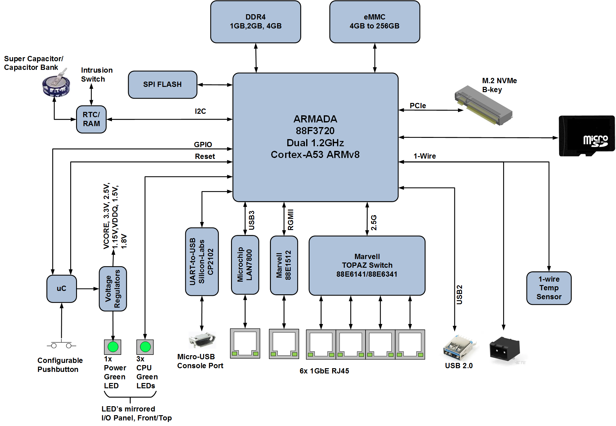
How the major components connect. The Armada 3700 uses its three SERDES lanes for 2.5G SGMII to the LAN switch, PCIe to the M.2 slot, and USB 3.0 to the WAN 1 Ethernet controller.
Hardware watchdog
An external watchdog implemented on a PIC microcontroller power-cycles the device if the SoC stops toggling the watchdog signal. Because it cuts power rather than asserting a reset line, it recovers the device from states a soft reset would not clear.
The timeout is programmed into the microcontroller at manufacture and cannot be changed in the field. It is set long enough to cover a normal boot, plus margin, before the operating system takes over toggling the signal.
Tamper detection and secure memory
The SG2v1 has an intrusion switch that is asserted when the top cover is removed. The device also has a small block of SRAM backed by a super capacitor rather than a battery, which holds its contents for roughly 26 hours without power.
Asserting the intrusion switch clears that SRAM. Opening the enclosure is therefore a destructive act with respect to the device's secure state, and the device is not intended to be opened in the field.
Caution: Do not open the SG2v1 enclosure. There are no field-serviceable parts inside, opening it clears the backed-up secure memory, and the microSD, M.2, and console interfaces inside are not customer-serviceable. Contact Scale Computing Support instead. |
Software
The bootloader runs from SPI flash. A first-stage bootloader brings up DDR, clocks, and critical hardware, then loads ARM Trusted Firmware to establish a secure execution environment before handing off to U-Boot, which loads the kernel from eMMC.
The operating system resides on the eMMC and is preloaded before the device ships, so no OS staging is required on site.
Installation and mounting
The SG2v1 is fanless and dissipates heat through its aluminum base and top fins. Both surfaces get warm in normal operation — the top overlay carries a May Be Hot marking for this reason.
Four mounting options are supported.
| Option | Notes |
|---|---|
| Desktop or shelf | Rubber feet on the base. Leave clearance above and below for airflow. |
| Wall mount | Keyhole slot with a secondary anti-lift screw, cast into the housing. |
| DIN rail | Screw bosses cast into the underside. DIN clips are ordered separately. |
| Rack | Rack-mount tray accessory, available separately. |
Observe the following when siting the device.
- Keep the device in an environment between 0 °C and +40 °C (32 °F and 104 °F). This range includes the external power supply, so do not enclose the PSU somewhere hotter than the device.
- Do not stack items on top of the device or block the fins on either surface.
- Use only the supplied 40 W power supply. The barrel connector locks — twist the collar to release it rather than pulling on the cable.
- Orient the device so the LEDs remain visible. If the I/O panel faces a wall, the mirrored top LEDs give you the same information.
What's in the box
| Qty | Item |
|---|---|
| 1 | Scale Computing SG2v1 edge security device |
| 1 | 40 W desktop power supply |
| 1 | AC line cord, regional |
| 1 | Ethernet cable |
| 1 | Printed quick-start guide |
| 1 | Single-unit cardboard packaging with adhesive product label |
Regional variants differ only in the AC line cord supplied: US, EU, UK, and ANZ cords are available.
Packaging
The device ships in a single-unit corrugated box with a folded insert that suspends it. The closed box measures 8.53 in x 6.30 in x 3.31 in (216.60 mm x 160.10 mm x 84.00 mm).
Labels and identifiers
Three markings identify a unit.
- Top overlay. Carries the serial number, an installation QR code, and the LED and port legend. Scanning the QR code with the Scale Computing Tech App streamlines SC//AcuVigil™ installs.
- Serial label. A 1.5 in x 0.5 in label with the serial number, its barcode, and the model or SKU number.
- Agency label. A second 1.5 in x 0.5 in label carrying regulatory marks.
The same model, SKU, and serial number label is applied to the shipping box, so a unit can be identified without opening the carton.
Record the serial number before mounting the device. Once it is wall-mounted or racked, these labels may not be readable.
Certifications
EMC
- FCC 47 CFR Part 15 Subpart B, Class A
- ICES-003 Issue 7 (2020), Class A
- EN 55032:2015 +A1:2020 +A11:2020, Class A; BS EN 55032:2015/A11:2020
- EN 55035:2017 +A11:2020; BS EN 55035:2017/A11:2020
- EN 61000-3-2:2014; EN 61000-3-3:2013 +A1:2019
- CISPR 32:2015 +A1:2019, Class A; CISPR 35:2016
- AS/NZS CISPR 32:2015 +A1:2020, Class A
- VCCI-CISPR 32:2016, Class A
Safety
- IEC 62368-1:2018
- UL 62368-1, 3rd Edition, 2021-10-22
- CAN/CSA C22.2 No. 62368-1:19, 3rd Edition, 2021-10-22
- EN IEC 62368-1:2020 +A11:2020; BS EN IEC 62368-1:2020 +A11:2020
- AS/NZS 62368.1:2022
- J62368-1 (2023)
Materials
- RoHS-6 (lead-free) and REACH compliant
Note: IEC 62368, EN 55032, EN 55035, and CISPR 32 supersede and include IEC 60950, EN 55022, EN 55024, and CISPR 22 respectively. |
Caution: Class A device. The SG2v1 is certified as a Class A digital device. It is intended for commercial and industrial environments and may cause interference if used in a residential setting. |